5P5T Danish VHF Contest Group
News, reports and articles
A closer look at the 5P5T TX-line
Posted by OZ1FDH
Tags:
After 10 years of 144 MHz contesting with 5P5T and continuously developing and changing the station, we figured that maybe it was time to do a thorough evaluation and measurement of the whole TX-line. In the TX-line design, we have taken care to keep the signal clean. This includes; choice of equipment with low phase noise, the transverter and driver PA are never used at more than 50% of their nominated output power and the final PA is never run at levels exceeding the nominated output. But we have to admit, that apart from on-air testing, we never measured if the TX performance actually was as good, we believed it to be. With the exception of a few flaws, where we knew some of the levels were wrong, we generally got nice reports on our TX signal. However, occasionally we also had reports that something was not quite in order, but we couldn’t really find anything wrong in the settings or design. Thus, it was time to seriously look into whether or not there was a problem, and we decided to do a full test of spectral purity and IMD.
SETUP
Back in 2007 when we were QRV for the first time in the Region 1 VHF contest, the basic 144 MHz station was an ICOM 756 PROII and a Kuhne TR+40 transverter. Later on, the HF station was changed to an ICOM 7700, and for the 2017 contest, the transverter is replaced with the Kuhne TR 144 Pro transverter. Thus, the current 5P5T station is built from a basic platform of an ICOM7700 and a Kuhne TR 144 Pro transverter followed by a driver PA and an GU78b tube amplifier or a BEKO HLV-1000 LDMOS amplifier.
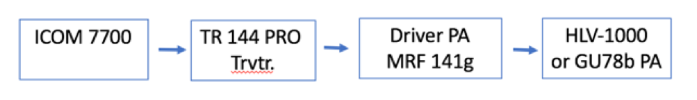
Figure 1. 5P5T 144 MHz TX-line
Phase noise specifications for the ICOM7700 TX and the TR144 Pro LO are shown in figure 2. Both the station and the transverter have good to very good phase noise specifications. With the ICOM 7700 having the highest phase noise, this defines the noise level.
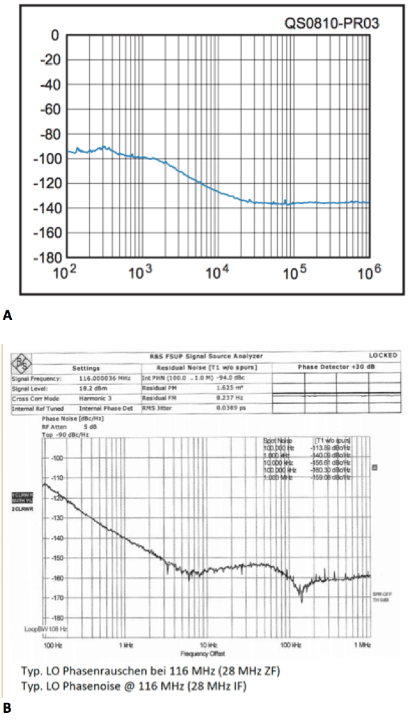
Figure 2. Phase noise a) ICOM7700 TX phase noise in dBC on 14 MHz at 200 W output measured by ARRL. b) Kuhne TR 144 Pro LO phase noise as measured by Kuhne.
To measure distortion products from all parts of the TX-chain incl. the QRO stages, we needed some heavier equipment than normally available. Birger OZ1GER is fortunate to work in a company servicing broadcasting equipment, and they were so kind to allow us to use their testing facilities.
I loaded the whole station in the back of the old Landrover - some of it can be pretty heavy (I am 53 years young….) and met OZ1GER Birger at his QRL. They do have equipment! Everything from Rohde & Schwarz spectrum analyzers, high power couplers to 10 kW dummyloads and lots of other type of RF equipment. I felt as excited as a little boy in a toy store, and my mouth began to water.
The setup we used for spectral purity and IMD tests was pretty much as described by the ARRL test procedures. As a two-tone generator, we used David Taylors SweepGen program setting the tones at 700 and 1900 Hz. Using the Laptop as audio generator may not be as good as a dedicated two-tone generator, but it sounded very clean and the scope showed a symmetric sinus signal.
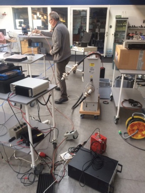
Figure 3. OZ1GER connecting all the boxes. Notice the grey “room heater” in the middle, it is a 10 kW dummyload.
MEASUREMENTS
First item on the bench was the new TR 144 PRO transverter. Kuhne specifies 3rd order IMD -37 dBm at 20 W PEP, we found -38 dBm, and when decreasing the output to 10 W PEP, the 3rd order IMD was a little lower than -40 dB, which is very good, just as the higher order distortion products were present only at very low levels. Testing all the way up to 30 W PEP just before the ALC light turned on, the 3rd order IMD was still as good as -36dB. The 144 PRO is really a very well designed high quality amateur radio equipment. On the other hand, it is not exactly cheap, but you do get value for your money.
Measuring the spectral purity, we found two spurious 600 kHz and 63 dB down on each side of the carrier, this is a native feature of the ICOM7700 and has been reported beforehand. We went on and tested IMD for the other parts of the transmitter chain, it all looked quite nice. Our MRF141G driver PA with 100 W out was nearly invisible with regards to IMD products. Adding the BEKO HLV-1000 or the GU78 PA increased the IMD products by a single dB or so. Trying to push the HLV-1000 into severe distortion products, the overload circuit simply turned it off before distortion started getting rough. Even the unmodified RFC 2-117 12 V PA at 100 W output surprisingly only gave another 2,5 dB of third order IMD products, pushing it to 150 W output, IMD increased 6-8 dB though.
Everything seemed to be fine, but there was something nagging in my mind, we still had these reports from amateurs who knew what they were talking about, that sometimes it wasn’t really “the sound of music” that we radiated from our antennas. On the other hand, when checking with the same amateurs on other occasions, we were told that it sounded very nice and clean.
OMG!
Coming back home I realised that we didn’t fully check the transverter output of the IC7700. During the testing, the drive level was left in the same position where we would normally run the 5P5T station setup. The drive control setting on the IC7700 front panel also regulates the output on the transverter terminal, and in our setup, it is normally always in the middle position. According to ICOM the transverter terminal delivers -20 dBm at full output, thus we should be well below anyway. Just to check it, I hooked up the two-tone generator, connected my old HP test rig and turned the drive to full output.
Before describing and showing the results, I need to add that the equipment at my home QTH is nowhere near what we used at OZ1GER’s QRL. There are no R&S spectrum analysers with fancy screen dumps or 10 kW dummyloads, just an old HP cellular phone test rig, with a low-resolution spectrum analyser, but it would have to do.
OK, I connected everything, adjusted the two-tone generator input on the IC7700, and took a look at the spectrum analyser……..OMG! WTF! this looked exactly like how my teenage son’s favourite heavy metal band sounded! On the screen was a full Christmas tree of every possible distortion and intermodulation product according to the books (Figure 4). The spectrum analyser resolution is so poor that it is not possible to determine the IMD products with any accuracy, but the 3rd order IMD was now something around -10 dBm, not to talk about the higher order products. What was going on here? It turned out that the power level on the transverter terminal was not -20 dBm as specified, but rather -13 dBm and even up to -10 dBm! Turning the level down to the specified -20 dBm it looked much, much better. Fiddling around with the settings, I could see the distortion products began to appear at around -18 dBm output, any higher than that, things turned very bad, very fast. Measuring on the transverter 144 MHz output (figure 5) and adjusting the transverter gain for equal output gave the same results; -20dBm and everything was fine, -10 dBm, and it was something you should not show to amateurs who has held a license for less than 25 years.
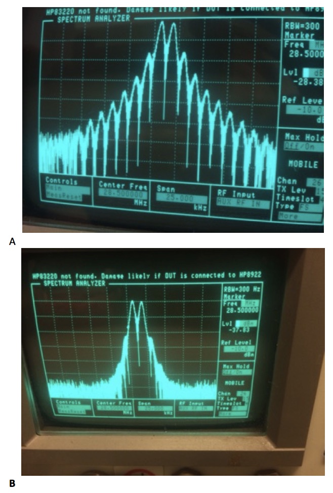
Figure 4. Two-tone IMD test on 28 MHz transverter terminal output on IC7700.
A) -10 dBm output B) -20 dBm output.
The transverter output is specificed for -20 dBm only, but can produce -10 dBm.
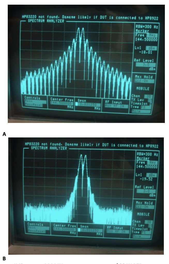
Figure 5. Two-tone IMD test on 144 MHz transverter output of 20 W PEP output.
A) -10 dBm full output from transverter terminal. B) -20 dBm specified output from transverter terminal.
The transverter does not add any distortion products, the problem is the signal from the HF station.
LESSONS LEARNED
I went back to the manual and service manual, read the descriptions and studied the diagrams, but couldn’t find any explanation for the much too high output level on the transverter terminal. Either there is something wrong with the settings in my IC7700, or there is a design flaw. In my shack is also an ICOM 756 PROII. This station does not have the same problem, max output is -17 dBm on the transverter terminal, and the signal looks nice and clean. (Note July 27 2017, AB4OJ reports the same high levels on the transverter terminal, it appears not to be a fault of my transceiver only http://www.ab4oj.com/icom/ic7700/7700notes.html)
Anyway, we probably found the cause for why we sometimes may have sounded rough on the edges, we never have the drive level set at full output, but if you adjust the setting just a few millimetres too high, you start turning out distortion products, and if signal levels are high, as they will be from a station like ours, it will create QRM.
The morale of this story is many fold; one is that we became wiser, another is to never trust the manual, and a third is there is no such thing as actually measuring what is really going on. Also, you may add that there are no fail-safe systems, and bringing your equipment in the field always changes parameters that you never paid any attention to back home.
Checking the linearity on-site is actually not that difficult; if you can bring a 2-tone generator and a portable spectrum analyser, you can monitor your on-air signal for IMD products, and make sure that all is OK. However, it does not guarantee that there will be no QRM from a big contest station like ours. With 19 dB antenna gain and a 1 kW TX, you can have the best TX with very low phase noise and only few IMD products, but if the RX at the other end suffers from overload or has a high LO phase noise level, then QRM will occur.
One example was from two amateurs in the same area about 45-50 km away, meaning line of sight from our QTH with a path loss of about 110 dB. Both had a HF/VHF multiband station and the same type of antenna. One of the stations reported no QRM of any importance from us, whereas the other station had us +/-200 KHz. The big difference between their stations was that one of them had a mast mounted pre-amp i.e. another 20 dB RX gain, probably causing QRM from the phase noise in the RX.
QRM in big contests can never be avoided, and of course you should always do whatever is possible to keep your TX clean. The challenge for a QRO station at a good QTH is that just the strength of your signal can cause QRM if the RX at the other side has too much gain or local oscillator phase noise.
By far the most QRM problems can be solved relatively simple, either at the TX or RX side. The most important thing is an open dialogue about the problems in order to find a solution, thus if you hear that 5P5T is causing QRM, please give us a report. We will always take it seriously, -there could be something wrong with our equipment.
Claus Felby OZ1FDH/5P5T