The region 1 VHF contest is usually a 2-month event around here. Come July we start checking and repairing equipment and antennas preparing for the contest 1st weekend of September. This year was different, as we started preparing one month earlier, all because of a lecture.
At the Nordic VUSHF meeting DF9IC Henning held a fantastic lecture about how DR9A had phased and rearranged their arrays not only in terms of electrical length but also in terms of radiation patterns making it as uniform as possible. The outset of their work was an observation that their combined radiation pattern had some pretty deep 10-20dB holes. The results of all their optimization work is quite clear, they are way ahead of everybody else in the big 144 MHz contests. You can watch Henning’s lecture here.
This started a lot of discussion among the 5P5T group. Could we modify rearrange our antennas along the same principles as DR9A?
Our basic setup was 4 systems; 2 times 8x3el, 4x3 el and 4x10 el. All DK7ZB designs. OZ1GER Birger started playing around with the EZNEC software. Could we simulate the combined radiation pattern of our antenna systems? The challenge simulating our antenna setup was that we did not have fixed positions for our antennas, from one year to the other we could move them several meters, neither did we have any idea about the phase relationship between the different systems. However, regardless how we moved them around in their previous positions it more or less looked liked the same. A broad pattern but uneven and with lots of deep loops, see figure 1. Remember, this is only a simulation not based on any measurements, but it certainly did look like there was room for improvements.
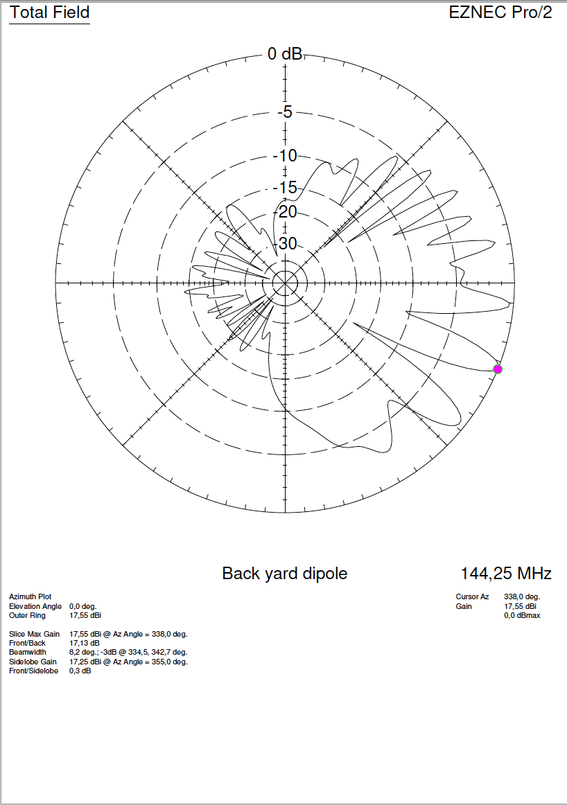
Figure 1. Radiation pattern of 5P5T antenna systems prior to 2018
Now we started playing around with the setup. Feeding all systems from one generator and with equal lengths of cable all the antennas simulated were in phase. We expanded the system that we would have 3 times 8x3 el, this was to be our main “broadcasting” antenna in fixed directions. The 4x10 el were placed more than 10 wave lengths away from the main array and were given its own separate TX and RX feedlines. We put all antennas on the same circumference and started varying the radius. Much like what DF9IC had found, the radiation patterns started coming together at a relative short radius of 1,5-2,5 meters. For practical reasons we settled on 1,8 meters radius. Also checking our simulations we could more or less gat the same results as DF9IC had shown for the DR9A 6 el antennas in his lecture.
The challenge was to obtain a broad pattern while preserving as much gain as possible. By varying the angle between the antenna systems, we found big variations. The 3 el antenna has its -3 dB points 57 deg wide, with a 40 deg angle between the antennas we got what looked like a pizza shovel with a less than impressive coverage. However, expanding to 60 deg. the radiation pattern looked more uniform and we had an acceptable loss of gain, see figure 2. Also quite interesting by combing two adjacent systems only we could get an intermediate pattern giving a peak between the systems, figure 2.
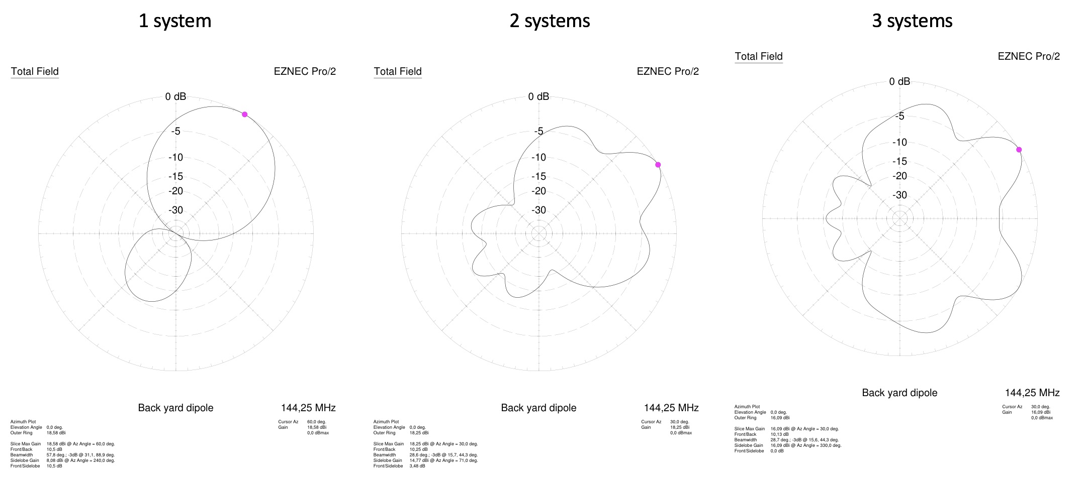
Figure 2. Radiation patterns from 8x3 el antennas, placed in an angle of 60 degrees in a circle with 1,8 m radius. One system, 2 systems phased and 3 systems phased.
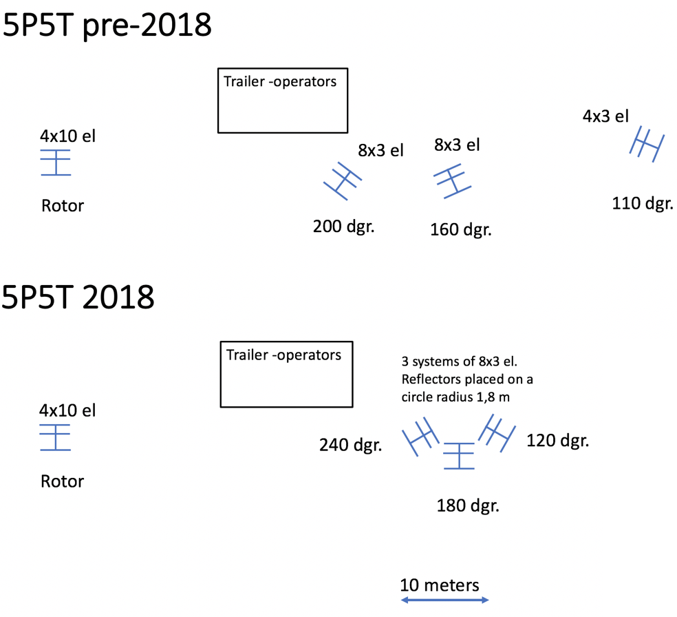
Figure 3. Antenna placement at 5P5T 2018 and pre-2018.
Having decided on the basic setup we started building extra antennas, new masts and made sure that all TX and RX lines were in phase. All cables and combiners were connected and we used a 200 MHz scope to compare the phase between the systems. By varying the length of the input cable to the PAs the phases were aligned on top of each other. Tuning the PAs varied the phase +/-15 deg which would only have a minor impact on the radiation pattern. Likewise, for the RX lines we varied the length of the cables from the preamps. On the TX side all 4 systems were run in parallel, using a 6 port wilkinson combiner after the driver PA, the TX-lines were isolated. Only the 8x3 el systems were phased, the 4x10 el were more than 12 wavelengths away and should only have minor influence on the radiation pattern. On the RX side we could listen to each system independently, 2 systems phased and 3 systems phased. The 4x10 el had its own separate RX-line. the RX antennas were all controlled from our fully analogue RX-switch box, figure 6.
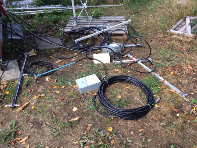
Figure 4. Cables, combiners and switch boxes connected for phase measurements at OZ1FDH QTH.
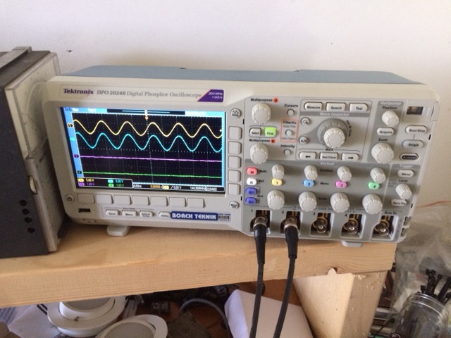
Figure 5. In phase -for now...
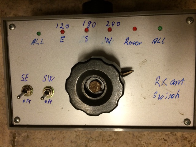
Figure 6. The analogue, non-Arduino, no touch-screen, all diodes and switches RX-control box.
The big BUT here is that, it is all simulations. The EZNEC software is advanced. But our new setup was only based on mathematical models and simulations, no real measurements were made. How would it work in the field in a real contest? Preferably we should have assembled it all at OZ1FDHs farm and measured the radiation patterns, but there simply wasn't enough time. Plans are that we will do the measurements later this fall.
All the usual preparations started packing equipment, making sure had not forgotten anything and checking that last detail one more time. Tough this was our 12th time in a row we were QRV you still need to pay attention to all the little details. This year we had a new power plant (figure 10), it tested fine back home, but would it stand up for 24 hours full contest load?
Assembling the station
From the Copenhagen area it is about a 2-hour drive to the contest site and we arrived Friday August 31 before noon. Thanks to the old Land Rover the operating trailer and generator made it to the top in the first try -the Eagle had landed! Following a bit of unpacking we followed our tradition and went for a good lunch of fried fish at Klintholm harbor.
Thereupon the real work started assembling the antennas and the station. Because the 3 times 8x3 el were to be put up in a specific pattern close to each other some extra thinking and arrangements were necessary. Come evening and 2/3 of the setup was ready, and the whole team OZ7UV, PA5DD, OZ1FTU, OZ5BD, OZ1GER and OZ1FDH called it a day and sat down for drinks (capirinhas) food and wine. Weather was perfect very little wind, no rain and we could enjoy good company and a wonderful view of the Baltic sea.
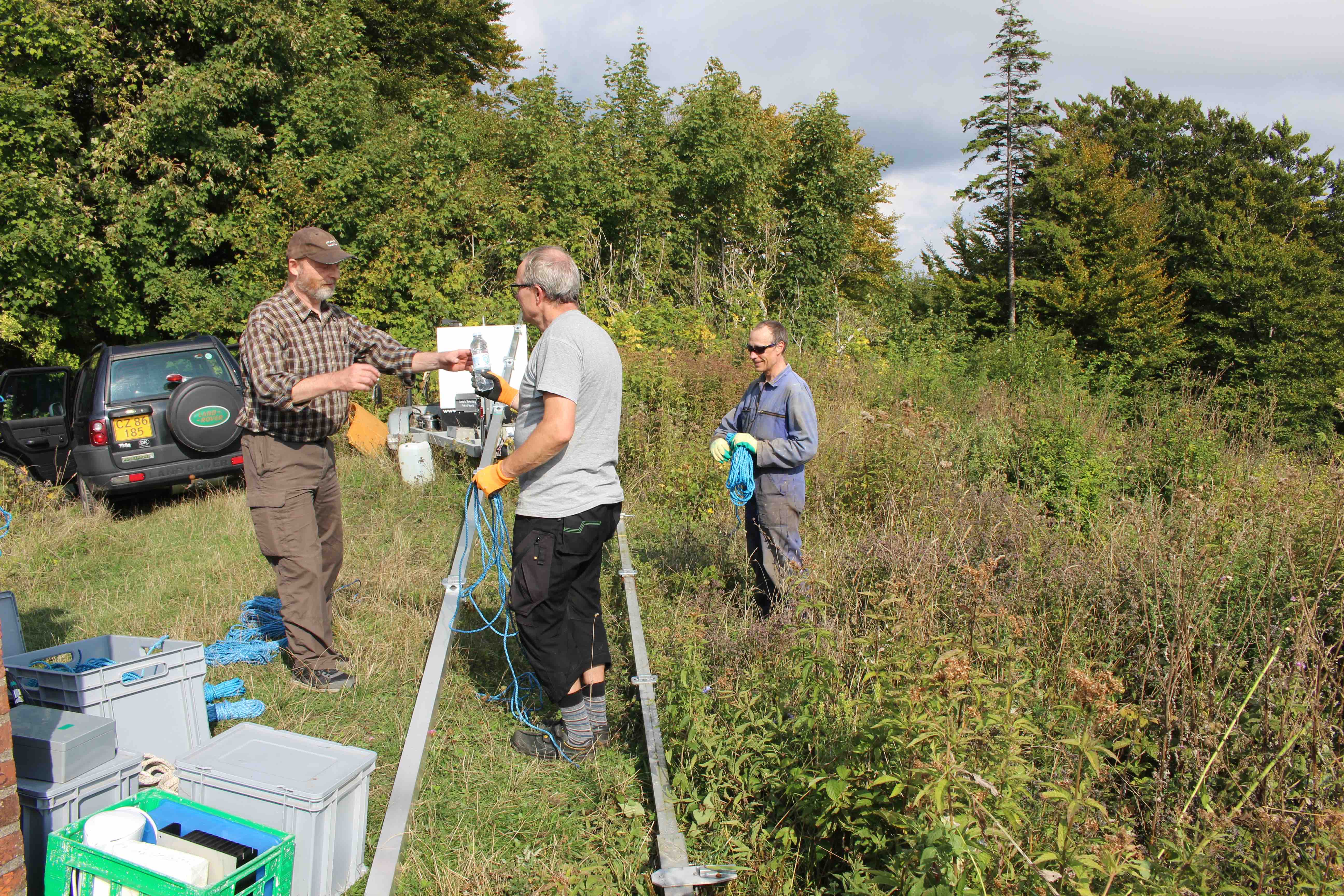
Figure 7. OZ7UV, OZ1GER and PA5DD antenna assembly. The very important Land Rover tool in the background.
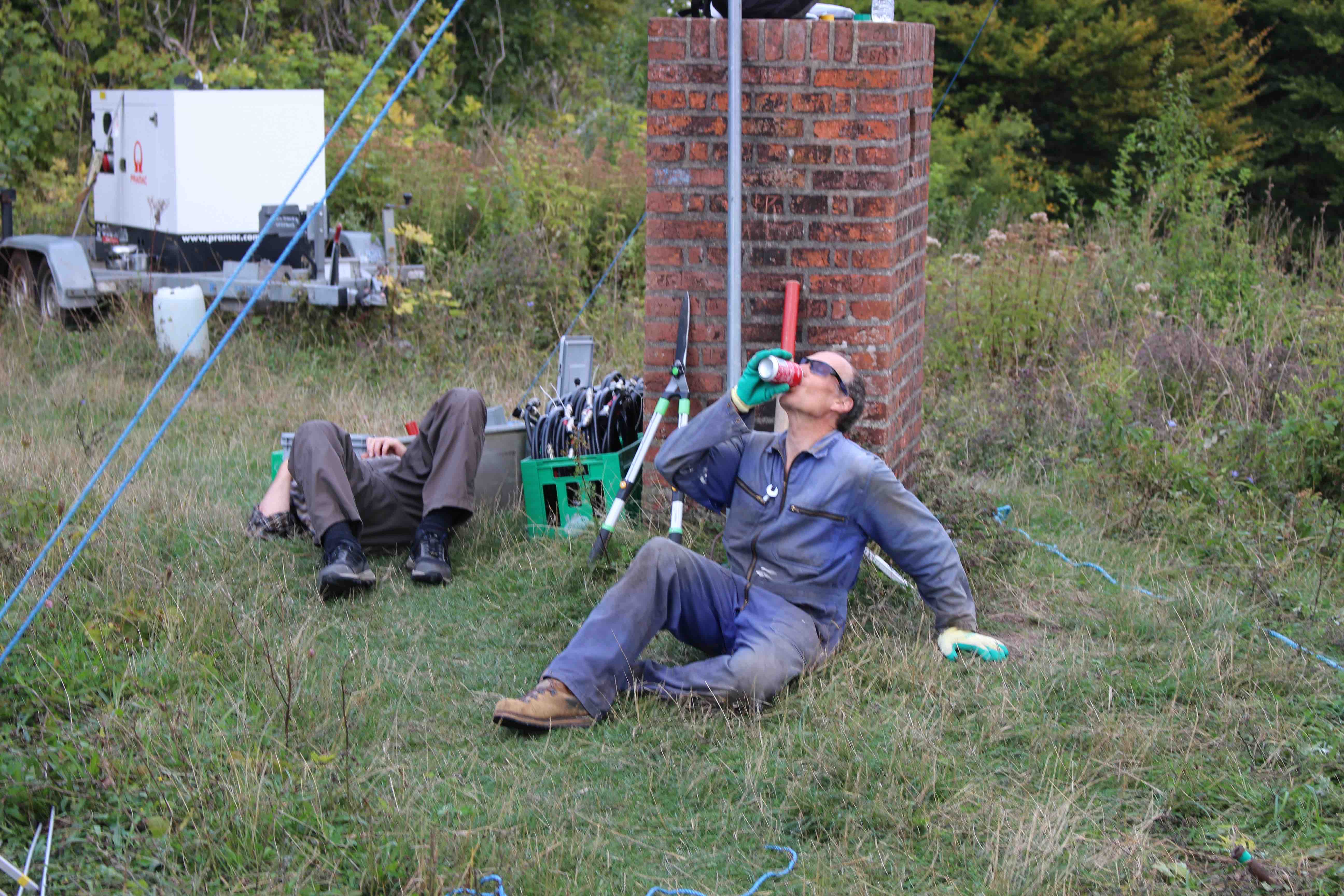
Figure 8. OZ7UV napping and PA5DD fuelling.
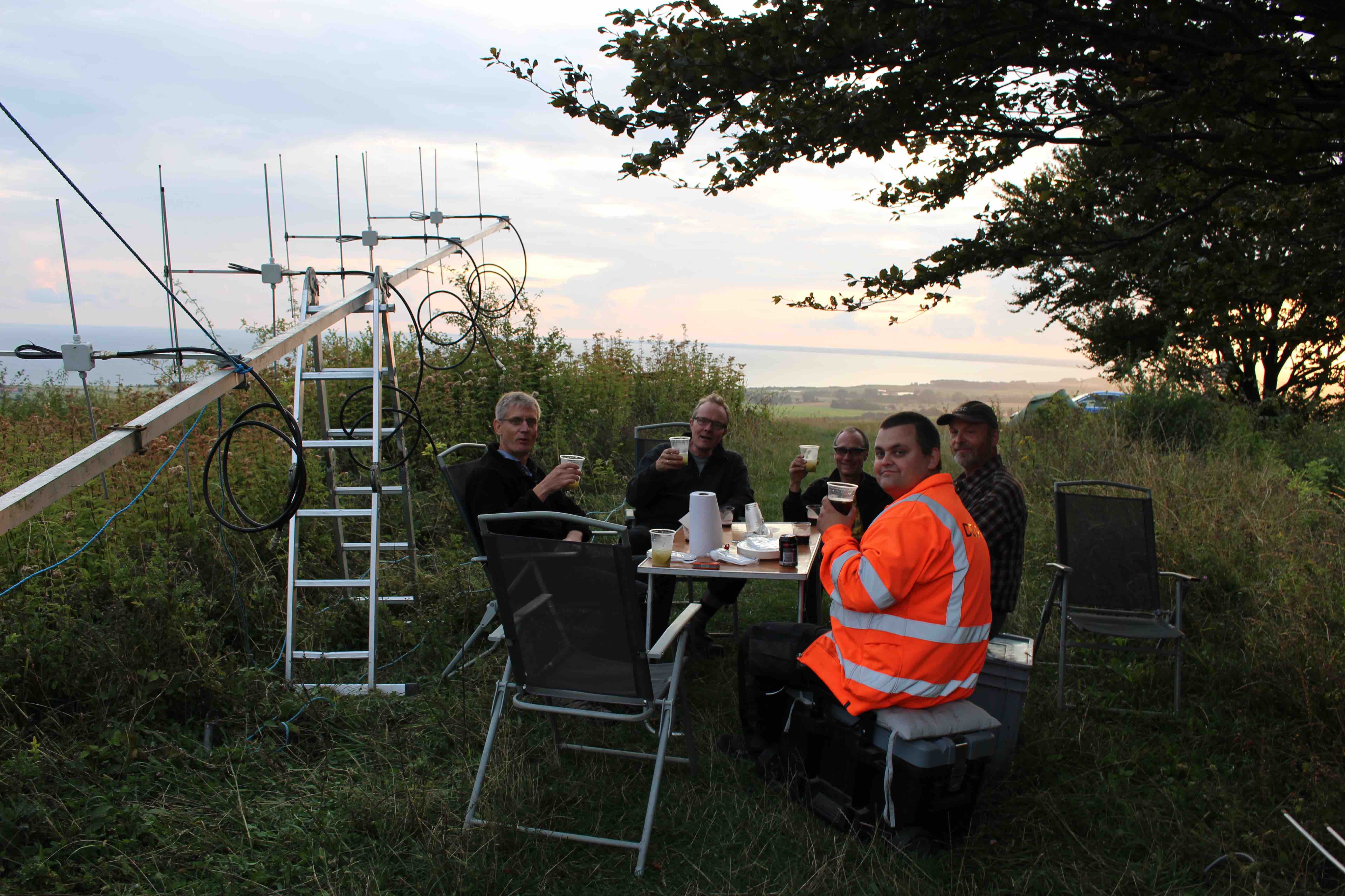
Figure 9. Drinks, food, antennas and good company
Global disaster looming!
Next morning we prepared for coffee and attempted to start the generator -but it couldn’t start! Following 2 min of panic we found that the battery seemed to be the problem, and again the old Land Rover saved the day. Transferring the battery form the Land Rover in the generator solved the problem. We could prepare coffee and hopefully also power up the station.
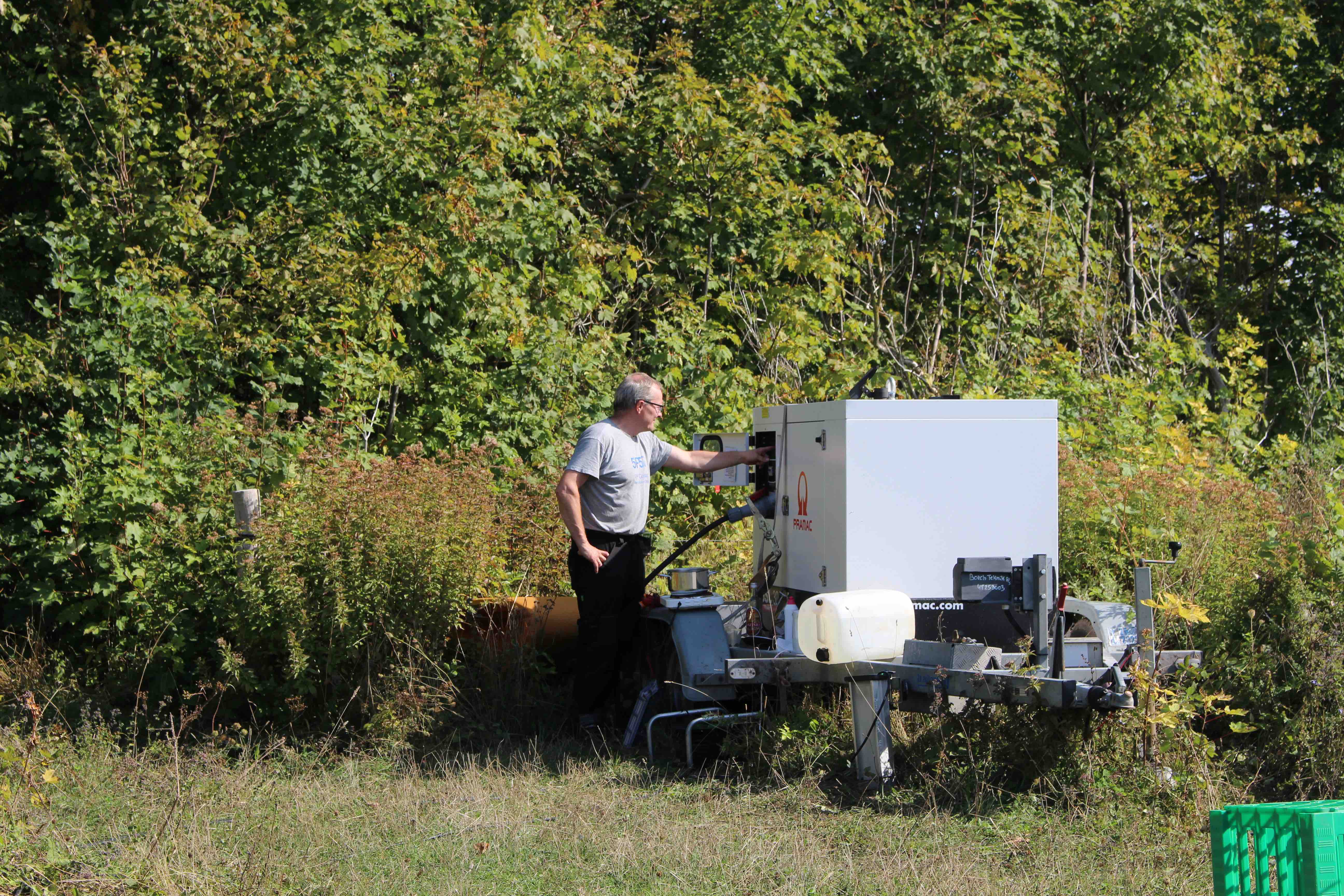
Figure 10. OZ1GER in crisis mode, getting the power-plant back on-line
Testing, testing and ???
Following coffee and breakfast, we continued and soon it was time for testing the big array. Did it work in real life? The quick answer is yes and no. Combining the systems pointing 180 and 240 degrees everything seemed to function according to simulations, but the third system pointing 120 degrees was odd. It couldn´t really pick up any signals. Lowering the system, we checked the preamp, it was perfectly fine, and now we became even more confused. With the system on the ground the antennas being vertical we could pick up beacons and raising the system to 45 degrees it became even better, but once the system was fully raised (90 degrees) the signals were almost gone. What was going on here? Was there some kind of interaction with the other 3 el systems that somehow cancelled the signal of the system pointing 120 degrees? Were the EZNEC simulations at all correct and missed near-field interactions? As you can tell there was a lot of guessing and very little actual knowledge and experience with larger phased arrays. We tried a number of things, inserting a ½ wavelength cable in the RX line of the 180 degrees pointing system making it counter-phase when combined with the 240 degrees pointing system lowered the signal around 20 dB, -yes the phasing did work! All appeared to be in order but there was something weird with our system covering southeast to east. After switching back and forth between systems, it was clear that only two of the systems worked as expected, but the time for the start of the contest approached and we had to make do with what we had. Maybe we some how could figure out what was the problem.
Another issue came up with the new generator. It was very sensitive for having a balanced load on all three phases, and it unexpectedly shut down a number of times during full load testing of the PAs. Pulling the big switch with hot relais is a recipe for blown pre-amps. Fortunately, in the power supply for relais and pre-amps there is a 40,000 uF capacitor on the supply side just keeping the system functioning for about 1 sec if you remove all power, and all preamps and relays survived.
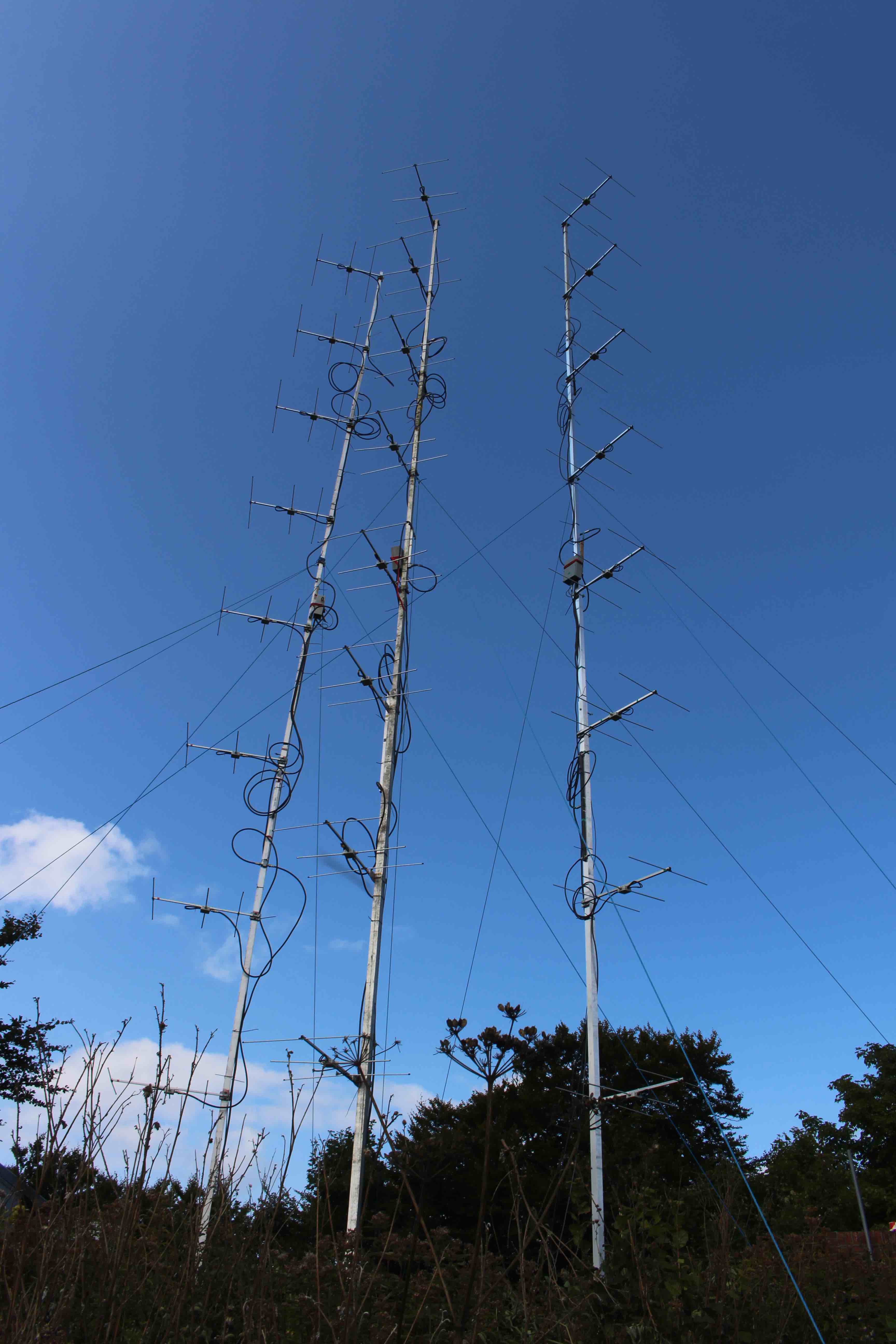
Figure 11. The combined array with 3 systems of 8x3 el
Contest time
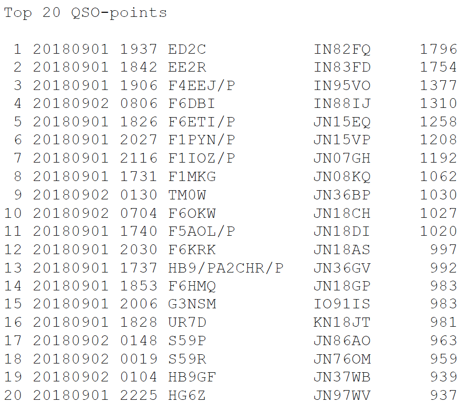
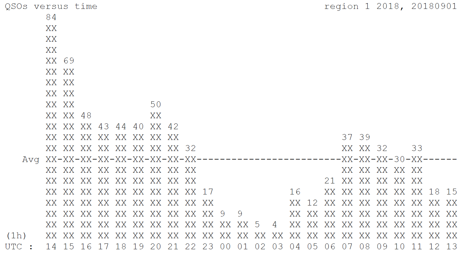
Hepburn had promised a little conditions to the south west, so it was with some hope that we started. 84 QSO’s the first hour is not bad, but short of our record from 2013 with 101 QSOs. The first 3 hours went pretty much normal. The longest QSO’s were in the 700-800 km range. Then at 17.40 F1MKG in JN08 1062 km called with a nice signal, followed 10 minutes later by F5AOL/p in JN18 1020 km, maybe something was cooking in the troposphere? About half an hour later F6ETI JN15 1258 km was in the log and then at 18.42 EE2R IN83 1754 km called! Wauv, this was serious DX, but the ODX was still to come when we worked ED2C IN82 at 1796 km.
We continued to fiddle around with the antenna system pointing east. SWR was fine and the preamp was OK, but it was almost dead as a brick, and we really had no idea what was wrong.
French stations continued to drip through the evening and both ED2C and EE2R were audible for hours, but no more Spanish stations were heard. There was a nice evening tropo lift to PA and ON, but to the south and south east it was more tough work and we definitely missed some stations to the malfunctioning eastern antenna system.
At the late hours the activity dropped as usual. We tried with quite a number of HG, 9A and S5 stations without any luck. We could hear them in most cases, but there was no responce. did it have anything to do with the "dead" system beaming east?
PA5DD and OZ1FDH, took the first night shift, and were replaced by OZ1FTU and OZ1GER at 2 am. At 6 am it was time for OZ7UV and OZ5BD to do the sunday crunch.
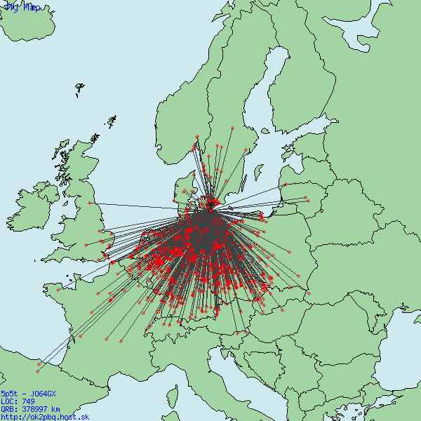
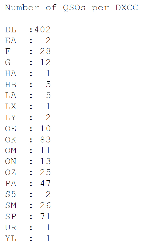
Sunday still produced some French stations, giving us a total of 28 French stations worked, definitely above normal. All in all, definitely a contest above average 749 QSOs, closet to 379,000 points in 22 DXCC’s and 104 locators. The nice DX contacts gave an higher overall score of 505 points/QSO.
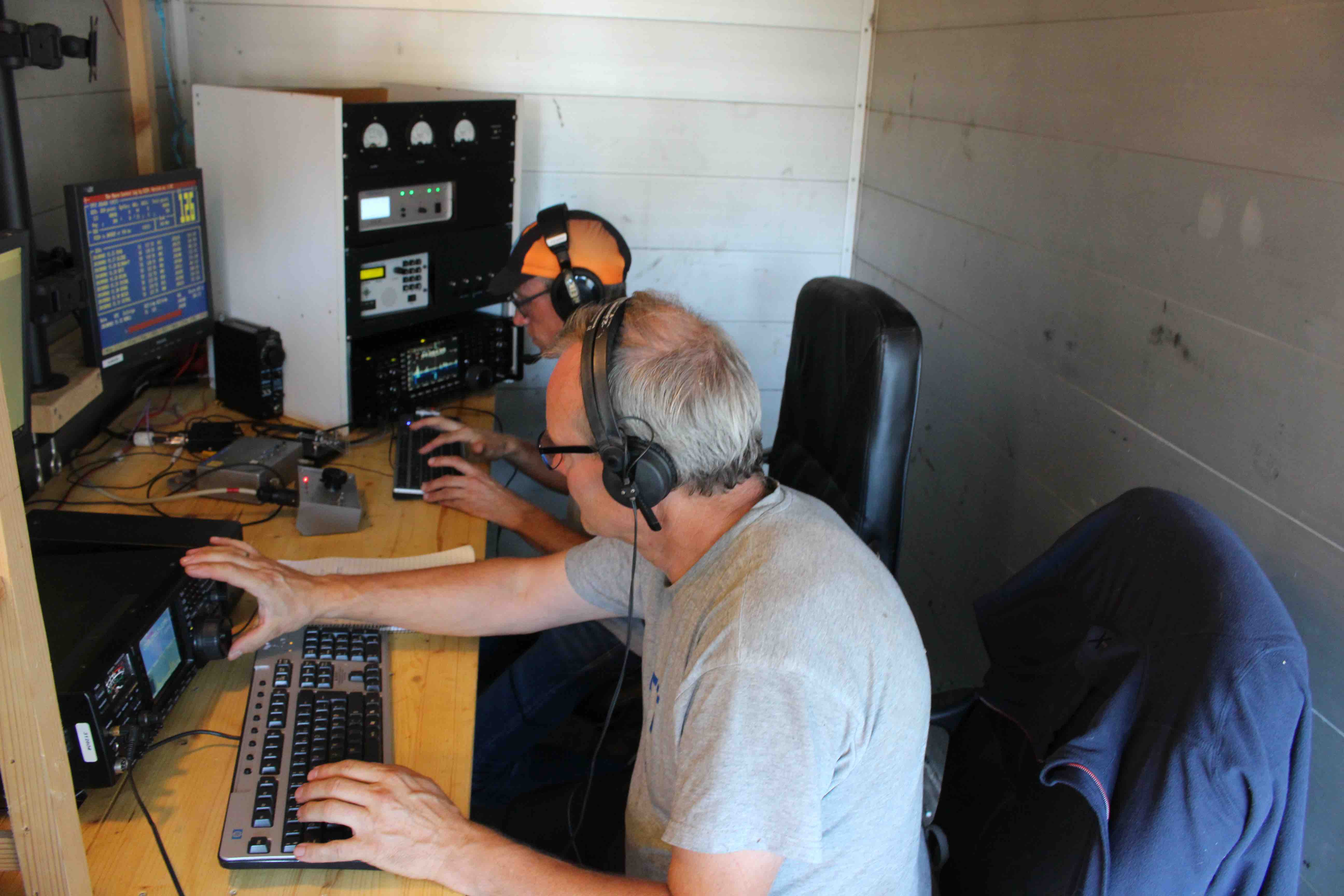
Figure 12. OZ1GER and PA5DD contesting.
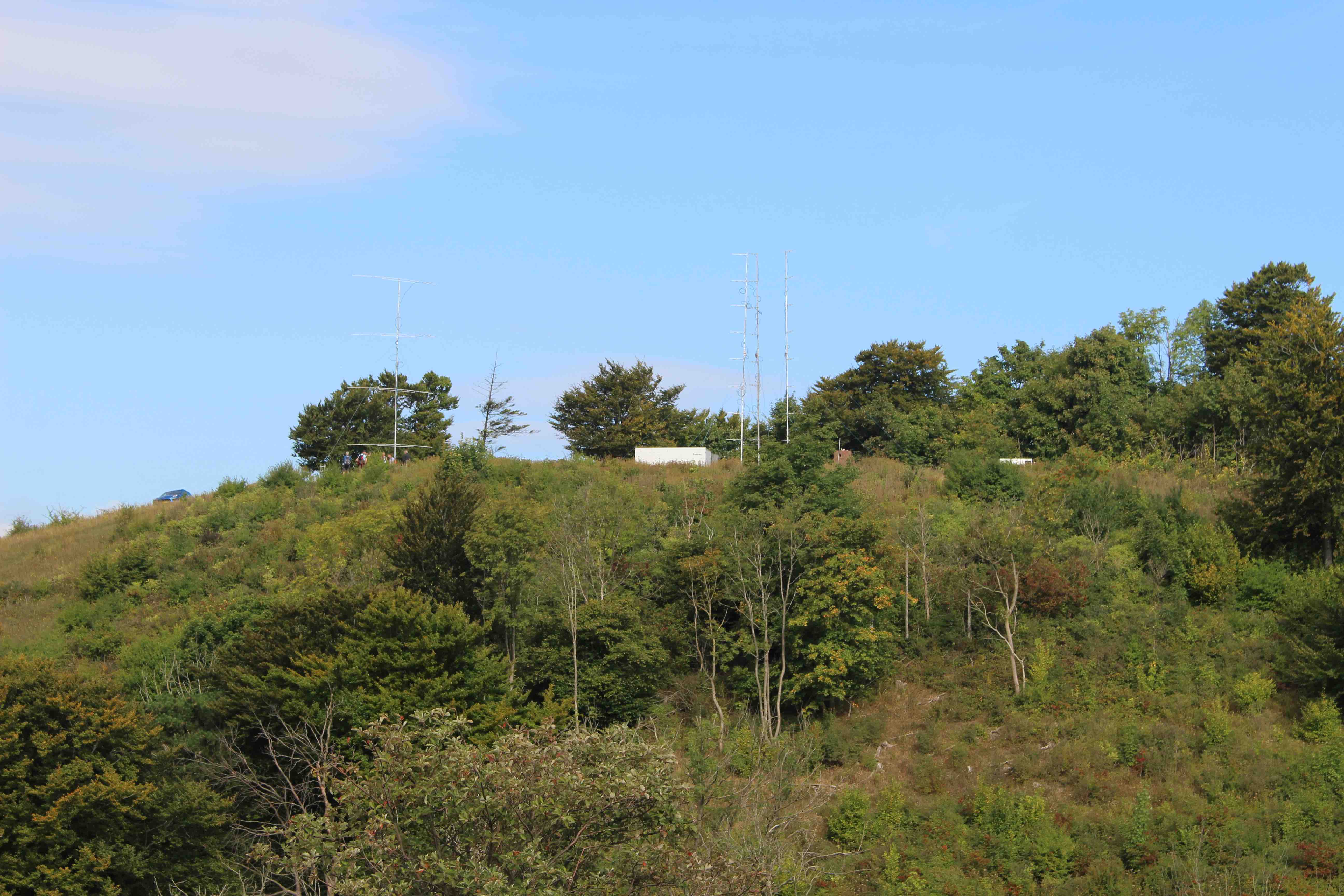
Figure 13. 5P5T camp seen from adjacent hill top.
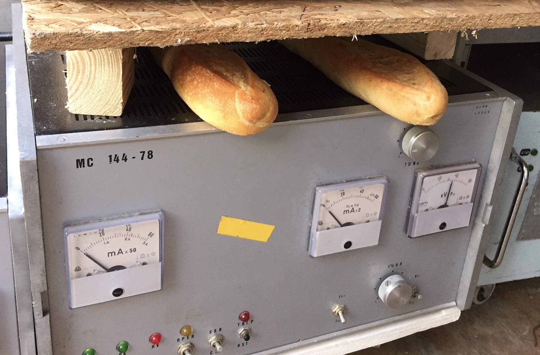
Figure 14. Waste RF-heat used for bread heater
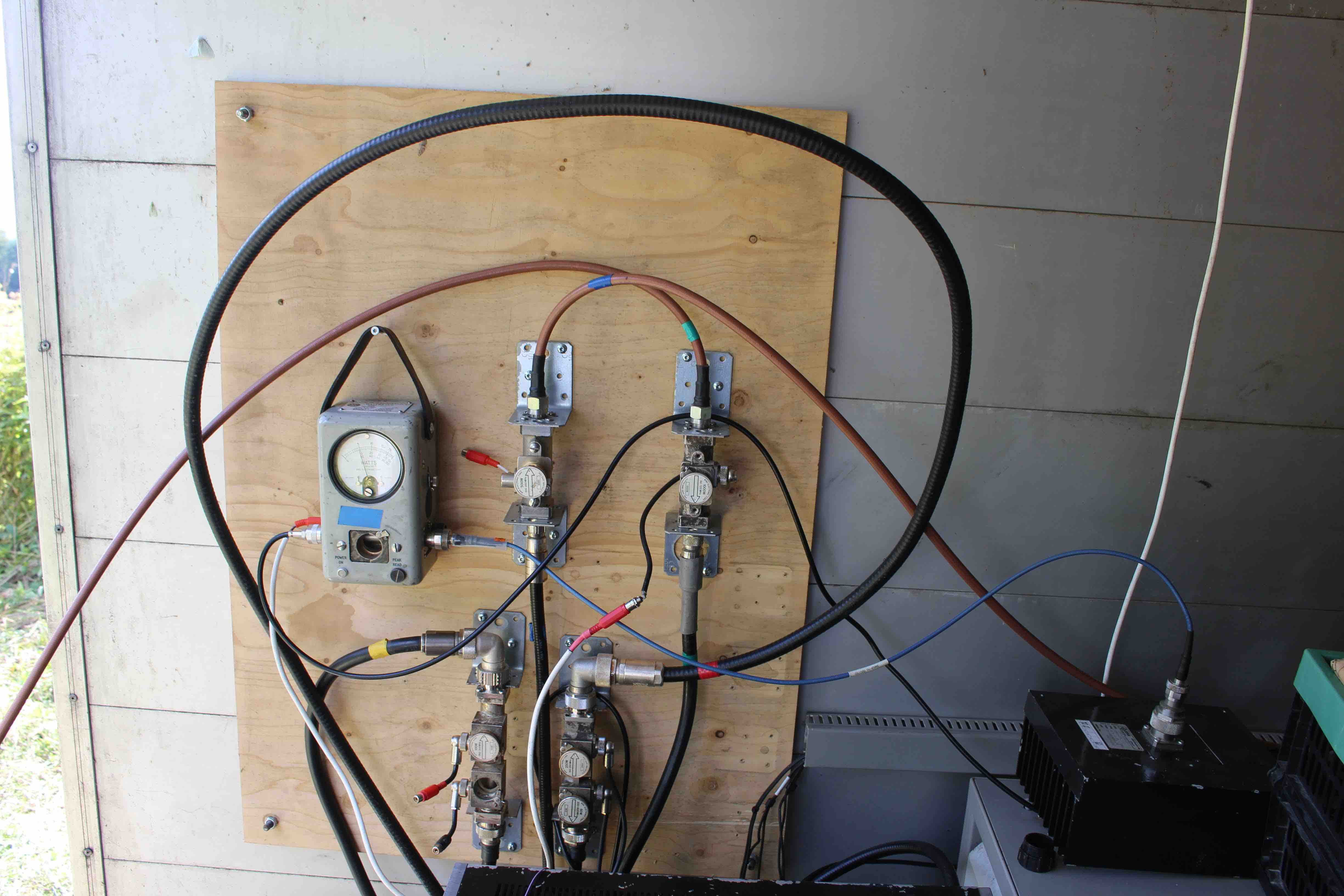
Figure 15. Cables, cables and couplers.
The revelation
A couple of days after the contest OZ1FDH had the pleasure of visiting his dentist for some jaw surgery. This must have somehow cleared his mind, because suddenly he realized what was wrong with the antennas. They were in counter-phase! The story was that 4 of the 3 el antennas were built 3 years ago, and the remaining 4 needed to complete the system was build this year. OZ1FDH took great care that they were identical to the antennas on the two other systems, but did not at that time look at the antennas he made 3 years ago. Checking the antennas, indeed that was the problem. The dipoles were feed opposite; thus, we had an antenna in perfect counter-phase. This very nicely explains why we had the best receptions of horizontally polarized signals, when the antenna was tilted 45 degrees. You can make fool-proof systems but you cannot make blithering idiot-proof systems
The preliminary conclusion is that the phasing and integration of the antennas do work, but we will need another contest or two to get the system fully aligned. How much did we loose from having an amputatedstem is hard to say, but probably in the order of 20-50 QSOs, which would have given us another 10-25 K points.
Regardless of all the troubles, we had great fun. We played with new ideas and build new antennas, we made mistakes, we made some extraordinary QSOs, we worked hard and became dog-tired at times but we had a good time together with good friends. This is really what amateur radio and contesting is all about.
Thanks for all the QSOs and we will see you next year again. Initial plans are for setting up the full system in next years July contest, but it depends the number of particpants available. Ham radio for ever!
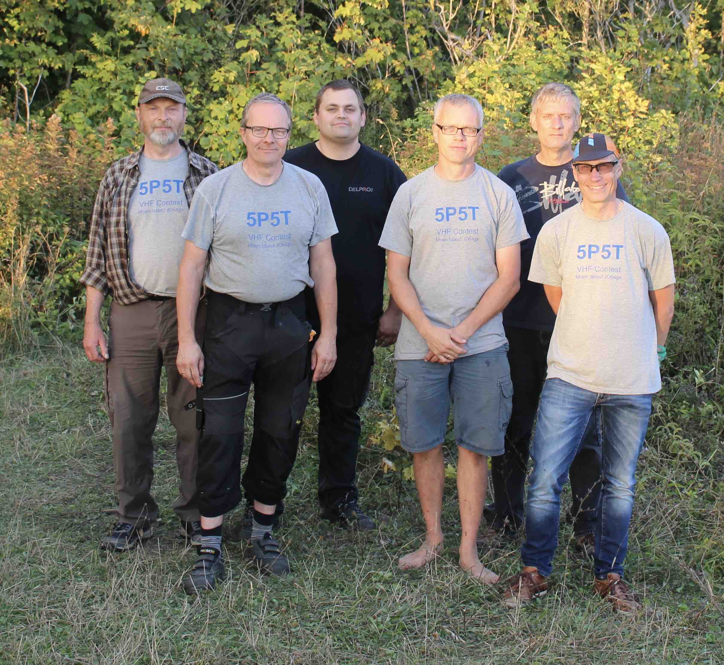
Figure 16. 5P5T team 2018. From left OZ7UV, OZ1GER, OZ5BD, OZ1FDH, OZ1FTU and PA5DD